
TopoR Version History
What’s New in TopoR version 6.2
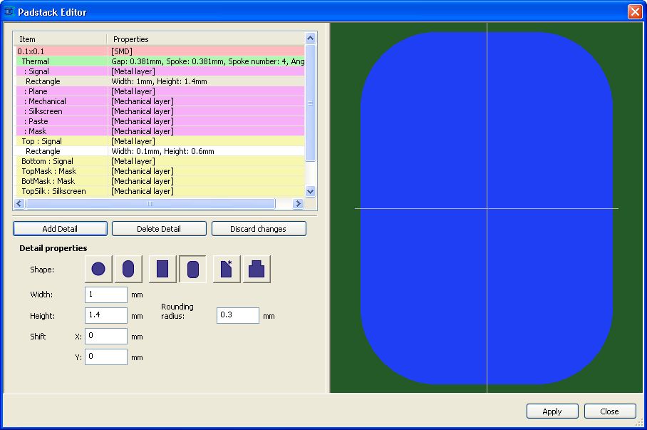
1. New pad shapes
a. Rounded rectangles
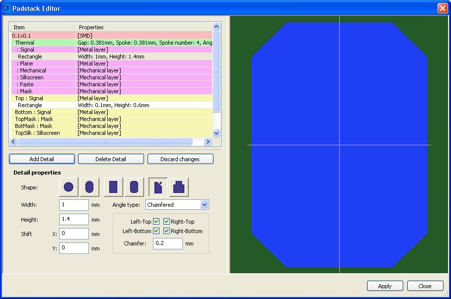
b. Sloped-angle rectangles
c. Finger pads
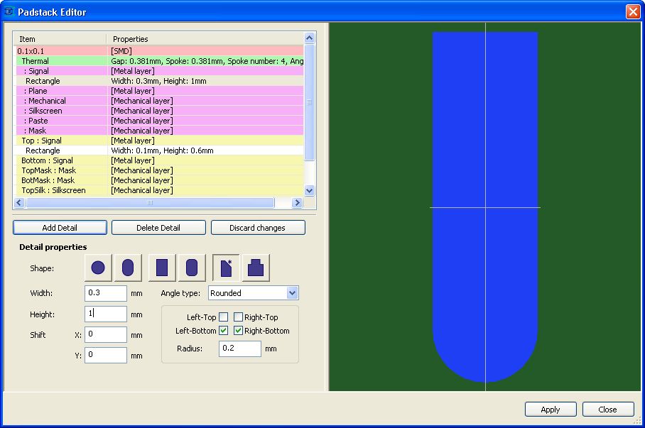
To set this shape for a pad, select the sloped-angle rectangle icon and specify the corner type in the element properties (rounded or sloped). For rounded corners, specify the bevel radius; for sloped corners, specify the slope value. Use check boxes to select which corners to apply the settings to. For example, the finger pad in the figure above is created by setting the type to rounded and the radius to half the width of the rectangle.
2. Wires can connect to pad corners
The Design menu now contains the Pad Connect Settings item, which opens the following dialog box:
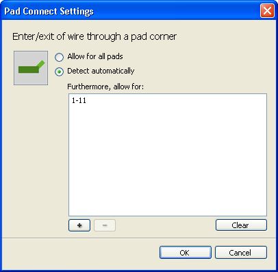
Click the + button to open an object selector where you can select padstacks or individual pads.
By default (in Determine automatically mode), only rounded and sloped corners can be connection targets on rectangles where the bevel radius is big enough.
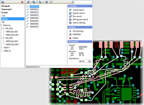
3. The netlist is now editable
There are two ways to edit the netlist for a net: by directly reassigning the net in the properties of a pad or by using the new Netlist item in the parameters editor:
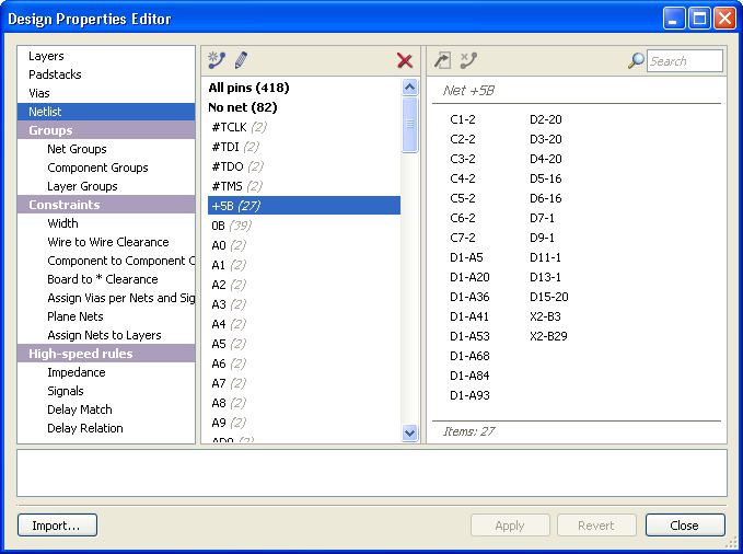
In the Netlist panel, you can remove pads from a net, move them to another net, rename nets, create new nets and remove existing nets. This enables you to edit the netlist directly in TopoR without involving external CAD software.
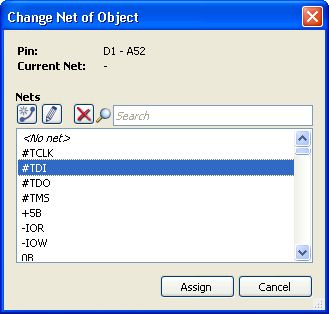
The following example shows how a net is reassigned for pad D1-A52 in the pad properties:
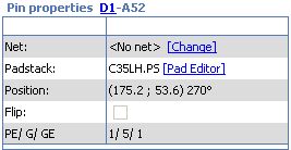
Clicking the Change link in the Net field opens the Change Net dialog box. Use it to select the net that the pad belongs to.
4. Other enhancements
- Support for designs in *.fsx format created by previous TopoR versions (6.0 and later). Designs can be saved only in the latest-version format.
- In addition to "absolute" cursor coordinates, relative coordinates are now displayed, meaning the offset from the last-clicked point.
- A default hotkey is enabled for the Only active layer option (Shift + S).
- Hotkeys are enabled for showing wires as thin lines (not defined by default) and for opening the Change Net dialog box (by default, Shift + N).
- The editor context menu now contains the Select Entire Net and Enable Flexible Fixing items.
- Double-clicking a DRC violation message selects the object that you can edit to eliminate the violation.
- Multi-layer routing improvements and speedups.
5. Miscellaneous changes and fixes
- Units are now set automatically for imported designs, according to the data in the source file.
- The state of the search window remains persistent after automatic procedures are performed.
What’s New in TopoR version 6.1
Version 6.0 was a major overhaul of how the system looked and worked. Version 6.1 continued and built upon the changes introduced in that version.
1. The quality of multilayer routing has improved significantly.
2. Automatic placement has been implemented.
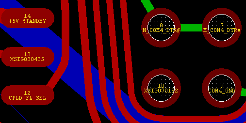
3. An option to display selected nets (signals, net groups) in a specified color has been added (Nets tab in the visibility control panel).
![]()
4. An option to selectively display net lines has been added (Nets tab in the display control panel).
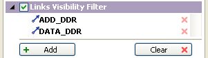
For details, see Display control panel.
5. "Staggering" of close-together DRC violations has been implemented.
6. The version of the TopoR PCB format has been updated. For details, see the TopoR PCB 1.1.3 format specification on www.eremex.com.
Designs developed in version 6.0 will open with slight data omissions in the current version; scrolling and scale parameters, color and visibility settings will be lost. To make sure all information is preserved, first export from version 6.0 to TopoR PCB format, and then import the result into version 6.1.
What’s New in TopoR version 6.0
1. User Interface
- The program’s look has been updated. There have been some changes to the toolbars and main menu.
- The project control panel has been updated. The Project History tab has been added. Projects are sorted by opening date.
- The Open Containing Folder command in Windows Explorer opens the folder with the selected file. The Copy Project command copies all project files to a folder you specify.
- The autorouting control panel has been added, where you can select nets for routing and change autorouting settings. The autorouting variant table is shown when you start autorouting.
- A control panel for the following automatic procedures has been added: calculation of wire shapes, wire route optimization, shifting of vias and components.
- The Options dialog box now includes the Hotkeys tab.
- Shortcut keys can be defined or redefined for most operations.
2. Topology Editor
- The editor toolbar has been updated. Related tools have been grouped. FreeStyle mode is now one of the editor tools. A new tool has been added for measuring the distance between objects.
- Arc-shaped wire segments are supported in all editor modes. In FreeStyle mode, multi-level undo is supported.
- There is a new context menu, where all possible operations on selected objects are available.
- In manual wire routing mode, automatic searching and highlighting of wires in the current layer has been implemented. You can accept the suggested route (this routes the wire automatically) or ignore it and continue manual routing.
- The object selection filter has been updated and extended.
- You now have the choice to automatically remove vias that have become redundant due to automatic procedures.
- Online DRC checks do not display bogus violations any more.
3. Design Properties Editor
- Automatic procedure settings have been moved from the editor to the corresponding toolbars. Editing settings have also been moved and are now available in the Editor Settings dialog box.
- Recently changed sections are now marked in the editor.
- The undo histories of the topology editor and the properties editor are now independent.
4. Autorouting
- Piecemeal routing without fixing the wires’ geometric shape has been implemented. Previously laid out wires remain flexible while the optimal wire shape is calculated.
- Differential signals can now be split automatically.
- BGA routing has been enhanced in that it is now aware of impedors located under the BGA component.
5. Other
- Data recovery after a crash has been implemented. If the crash occurred during autorouting, then autorouting results are also recovered.
- The TopoR PCB format has been updated. For details about the changes, see the specification for version 1.1.2 of the format.
- All designs developed in TopoR versions prior to 5.2 can be transferred to the current version. For that, export your design from the old version to the TopoR PCB format, and then import the resulting file into TopoR 6.0.
What’s New in TopoR version 5.4
Version 5.4.14421 on 03/12/2013
- If you click on the warning / error / advice message the wires are highlighted not considering the layer visibility.
Fixed:
- PCAD export. Rectangular parts on mechanical layers were not saved in the export file.
Version 5.4.14362 on 02/07/2013
- In the warning about noncompliance delay equalization of signals, the information about the appropriate length is added along with the information on the amount of delay.
Fixed:
- During import of Eagle BRD-files:
- in some cases the angle of rotation of pads was disregarded
- in some cases the vias’ pad size was assigned incorrectly
- sometimes the wires on the inner layers were disappearing.
- The clearance specified for individual nets was not taken into account during the DRC check.
Version 5.4.14288 on 22/1/2013
Beta testing is over and we are pleased to announce the release of TopoR 5.4.
Fixed:
- Wire width check in DRC sometimes caused the program to crash.
- Signal delay equalization on some multi-branch differential pairs was at times miscalculated.
- Pin pairs could were not added on the Bus Search panel.
- In some cases, the diff.pair recovery procedure did not work.
- Improper processing of copper areas that overlapped and belonged to the same net.
- Hyperlinks in tutorial Help ► ‘Hot Keys’and Help ► ‘Specifics of Using the TopoR System’
See also the list of the changes introduced in the beta 5.4.14203
Version 5.4.14203 on 21/12/2012
- The topology editor view can now display the names of pads and pad nets. To manage the display, use the Pin names and Net names check boxes, which are located on the Objects tab of the Display control panel. By default, both check boxes are selected.
- A new tool has been added for restoring differential pairs of wires. Its primary purpose is to restore information about differential pairs that were previously created in the TopoR CAD system. This information is lost during export to other CAD systems, so it needs to be brought back during re-import into TopoR. Running the Restore diff pairs procedure will make the information available again, and the wires involved will become zipped. For this procedure to work, the design must have the necessary differential signals defined. The procedure runs automatically during import and can be launched manually by clicking Tools ► Restore diff pairs in the main menu.
- The Eagle BRD plain-text format is now supported. This format is used by files created in the Eagle 6.0 system.
- The Resolution parameter has been added to .ses file export settings; the parameter specifies the coordinate precision. A new template has been introduced for CADint support.
- The version of the TopoR PCB format has been updated. For more information about the changes, see the specification of the TopoR PCB format version 1.1.1.
- Designs made in version 5.3 will open in the new version with minor data loss. The following parameters are affected: scrolling, scaling, color settings and visibility options. To make sure that all information is retained, you should first export the design from version 5.3 to TopoR PCB format, and then import the resulting file into version 5.4.
What’s New in TopoR version 5.3
Version 5.3.14009 on 16/11/2012
- Fixed a bug that caused a crash when exporting into PCAD.
- Fixed PCAD import bug, which, in some cases, led to a crash.
- Fixed PCAD import bug, which led to a net appearing at the mounting holes.
- Fixed autorouting bug. In some cases, fixed vias in BGA area were accounted improperly.
- Fixed sorting objects in the lists and tables. After C1, shall be C2, and not C10.
- Help updated. Added index and search features.
Version 5.3.2.13839 on 10/17/2012
- Information about the number of SMD and through pads is added to the Statistics window with.
- Now at the completion of manual wiring in any place the recently added via is not removed.
- Fixed PCAD import of board outline consisting of straight lines and arcs.
- Fixed a bug that cause hanging-up during the autorouting.
- Fixed wrong objects highlighting when selecting DRC violations.
- Fixed a bug that caused a crash when creating signals.
- Fixed a bug that in some cases caused miscalculation of signal delay.
Version 5.3.2.136 74 on 09/11/2012
- In the Manual Editing mode it is possible to delete a wire dogleg by moving a via in the immediate vicinity of the dogleg.
- In the Manual Editing mode it is possible to delete a copper area outline fracture by moving the vertex in the immediate vicinity of the fracture.
- In the search:
- for each stack of pads the number of contacts with each stack is shown in the brackets;
- for each type of vias the number of each type is shown in the brackets.
- Fixed: Incorrect record of functional equivalent pins during export to PCAD with prototype.
- Fixed: Incorrect sorting in the Design Properties Editor tables in the presence of
fixed-point numbers. - Fixed: Export of
arc-like sections of wires into Expedition.
Version 5.3.2.13430 on 06/28/2012
1. For the objects grouping a new ability is added: exclude an object from the group by dragging it onto the ”ungrouped” element of the navigation bar.
2. The primitives of fixed components on the mechanical layers are shown with dimmed colors. For the old projects it’s necessary to pick the layer color one more time or choose a color scheme, otherwise the primitives will not be dimmed.
3. When choosing a new color by clicking ”More colors”, the initial color is set to be the current color.
4. Multiple selection for setting the properties of nets and group of nets is added in the Design Properties Editor (Net properties).
5. Changes in Drill- files export. Now the holes with different diameters are written to the same file. Allocation onto files is carried out over a range of layers, and on the basis of metallization.
6. An error during the converting of wires into copper areas, that lead to the program crash, is fixed.
Version 5.3.2.13213 on 05/21/2012
1. A hot key is added — "Z" to pour/unpour the copper area.
2. Highlighting of the selected signal connections is added.
3. The status bar displays information about the selected signals.
4. The status bar displays information about the nets belonging to groups.
5. Fixed data loss of the nets connected to mounting holes when importing from PCAD.
6. The form of pads for export to PCAD is replaced by 'Ellipse' (used to be 'Oval').
7. Fixed diff. pairs attribute errors when exporting to PCAD.
8. Fixed problem with exporting small arcs into PCAD.
Version 5.3.2.12 953 Beta on 04/09/2012
- Differential signals, groups of nets, groups of signals and groups of components are added in Search Panel.
- When selecting objects from the Search Panel, selection filters are taken into account.
- Sorting by name/ shape/ hole diameter/ size is available for the pads in the Design Properties Editor, "Padstacks" page.
- User Guide changes: updated section – "Design Properties Editor – Object Grouping"
- Fixed bugs:
- import of design parameters
- signals search

Version 5.3 Beta
1. "Signal" is a new object type introduced for signal transfer.
A signal is a series of wires and (passive) two-terminal elements. The introduction of signals helps provide more accurate baseline data (compared to version 5.2 and earlier) for solving the problems of delay synchronization in transmission lines. The differential signal configuration method has been revised.
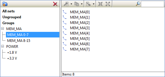
2. In the design parameter editor, the user interface for object grouping has been heavily updated.You can now create hierarchical group structures.
3. In the design parameter editor (F4), copying of parameters from another design has been added. Parameters can be copied from .fsx design files and .fst TopoR PCB files.
4. In the topology editor (F7), you can now copy and paste objects (keepouts, coppers, board outlines, parts on mechanical layers, texts, vias).
5. The wire shape optimization algorithm has been improved. The number of DRC violations has been greatly reduced.
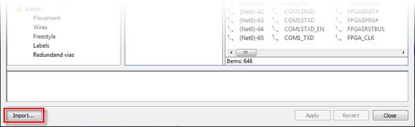
6. You can now select nets and layers for wires-to-polygons conversion.
![]()
7. Mechanical layers can now be included in placement calculations.
8. Project workflow has been improved:
- You can create a project after the import wizard completes.
- The state of project files is monitored in real time.
9. Design files can be opened directly from Windows Explorer.
10. The version of the TopoR PCB file format has changed. For details, see the specification of version 1.1.0 of the TopoR PCB format.
11. To transfer a design developed in version 5.2 to the new version, first export the design in TopoR PCB format using version 5.2, and then import the resulting file using version 5.3.
New Features in TopoR
New Tools
- Synchronization of delays in signal transmission lines
- Specialized open TopoR PCB file format
- Conversion of wires to polygons
- Copying of files from another design
Autorouting
- Autorouting using non-through vias
- Improved wire shape optimization
- Resolution of "clinches"
- Keepouts for vias
User Interface
- Redesigned object grouping
- Copying and pasting objects in the topology editor
What's new in TopoR version 4.0
- Communication with other CAD software via DSN/SES files. It's possible now to replace the SPECCTRA & ELECTRA autorouters.
- Export to PADS.
- Wires can be presented by lines without arcs.
- DRC is available in the "Manual routing" mode.
- You can view detailed descriptions and highlight objects (wires, pads, vias) that cause DRC violations by clicking DRC objects.
- You can create polygonal metal areas and keepouts.
- You can create and edit text labels on the board.
- Object selection has been improved. You can easily select objects from a list.
- Selection filters allow you to disable selection of undesired objects.
What's new in TopoR version 3.0
Autoplacement mode (F5)
- Automatic component placement (press F9 or the Start button on the toolbar) has been considerably improved. In previous versions, components often overlapped. Placement keepouts have not been implemented yet.
- The search panel has been added. It allows you to search for components, nets and padstacks by name or substring.
Autorouting mode (F6)
- Support for wires with fixed geometry and fixed vias has been added
- The text in signal layers is considered during routing
Manual editing mode (F7)
- Undo for all editing commands.
- The search panel has been added. It allows you to search for components, nets and padstacks by name or substring
- Support for wires with fixed geometry and vias has been added
- Manual switching of functionally equivalent pins (Pin Swap)
- Multiple selection of wires and segments
- User can choose how to highlight selected objects: by colour or by brightness
"FreeStyle" editing mode (F8)
- Optimization of topological routes for wires (refine) during automatic movement of components and vias (press the Start button on toolbar)
- The search panel has been added. It allows you to search for components, nets and padstacks by name or substring
- Support for wires with fixed geometry and vias has been added
- Consideration of text on signal layers and silkscreen layers
The following features have been added:
- Export to DXF format
- Generation of GERBER files
- Generation of ECO files
- Output of all coordinates and sizes in uniform units