
High-quality autorouting
TopoR ensures the exceptional autorouting quality
Isotropic routing with arcs ensures the most effective usage of boards’ surface
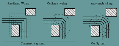
TopoR topological router is distinguished by having no preferred routing directions, which are divisible by 45 degrees. Any-angle routing ensures more efficient space usage.
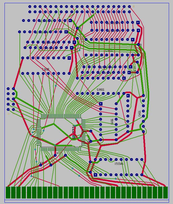
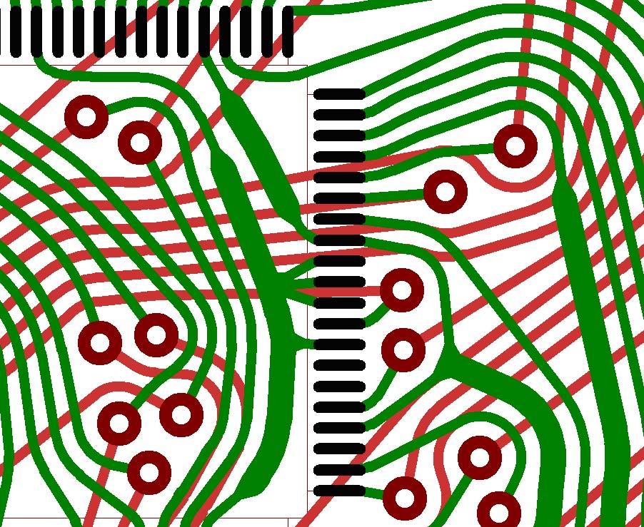 Topology fragment routed by TopoR CAD system.
Additional advantage is provided by using routing with arcs and arc approximating lines.
 The whole board surface is used more efficiently when using arcs.
In many cases it is routing with arcs that can ensure the maximum possible and at the same time equal conductor spacing. This can be critical for example for differential pairs.
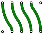 This is the only possible variant of routing with maximum conductor spacing. In case of using 45 degrees routing the spacing is unequal and their dimensions are 30% less.
Thus, the any-angle routing with arcs, provided by TopoR, ensures the most efficient usage of boards’ surface.
TopoR supports two modes for the optimal routing of single-layer boards
TopoR CAD system is the leader in providing highly-optimized algorithms of single-layer PCB design. The results which are comparable to manual routing can be achieved due to usage of efficient algorithms for minimizing the quantity and length of jumpers. The most widely-spread CAD systems including the best ones cannot fulfill such tasks.
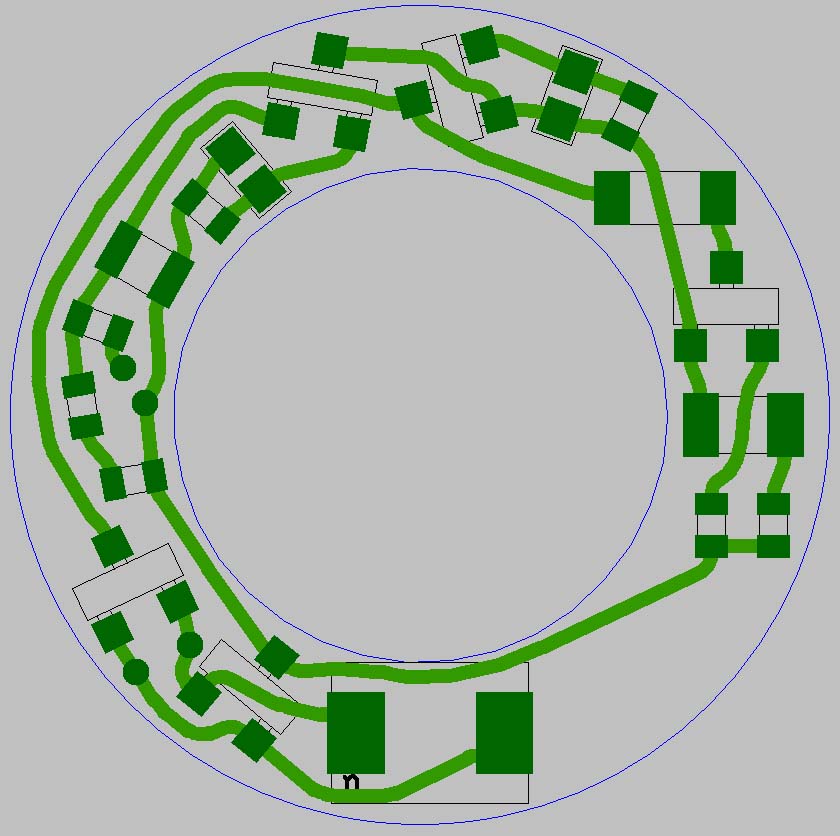 TopoR has automatically routed a single-layer PCB without jumpers in less than 1 second.
 A high-class Shape based router was unable to fulfill the task (only 56,3% of circuits were routed).
TopoR is the irreplaceable tool for flexible PCBs design
TopR is capable of minimizing the number of vias which makes it the preferable autorouter for flexible PCBs design.
Flexible PCBs consist of the sets of interconnect wires which can contain single-layer, two-layer or multi-layer structures. The boards can be as completely flexible so representing a combination of flexible and hard components. Typical requirements for wires in the flexible part of the PCB include:
- perpendicular alignment towards the bending direction;
- staggered positioning on the neighboring layers;
- no metalized vias are allowed;
The image below shows a flexible PCB topology which was made by a popular Shape-based router. We should note the presence of vias in the bending part, significant number of wires which are positioned closely under each other on the neighboring layers, and the segments of wires which are angled at 45 º towards the bending direction.
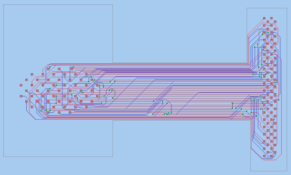 A flexible PCB topology produced by a popular Shape-based router (overall wires length is 346 inches, number of vias– 61).
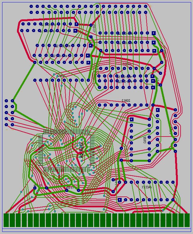
The same board routed by TopoR does not contain vias and at the same time has smaller overall wires length.
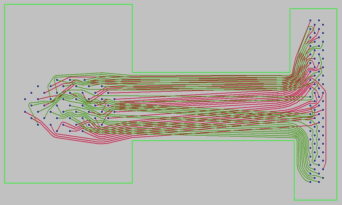 A flexible PCB topology offered by TopoR (overall wires length is 322 inches, number of vias– 0).
TopoR CAD system ensures significant reduction of vias and the overall wires length in comparison with other PCB CAD systems.
Using unique routing algorithms, TopoR CAD system provides unsurpassed characteristics in minimizing the number of vias and total wires length on the designed board.
As a result, TopoR allows to design the same PCB with less number of layers and/or having less size and/or becoming more cost-effective and/or providing better electromagnetic compatibility particularly due to increased spacing between wires.
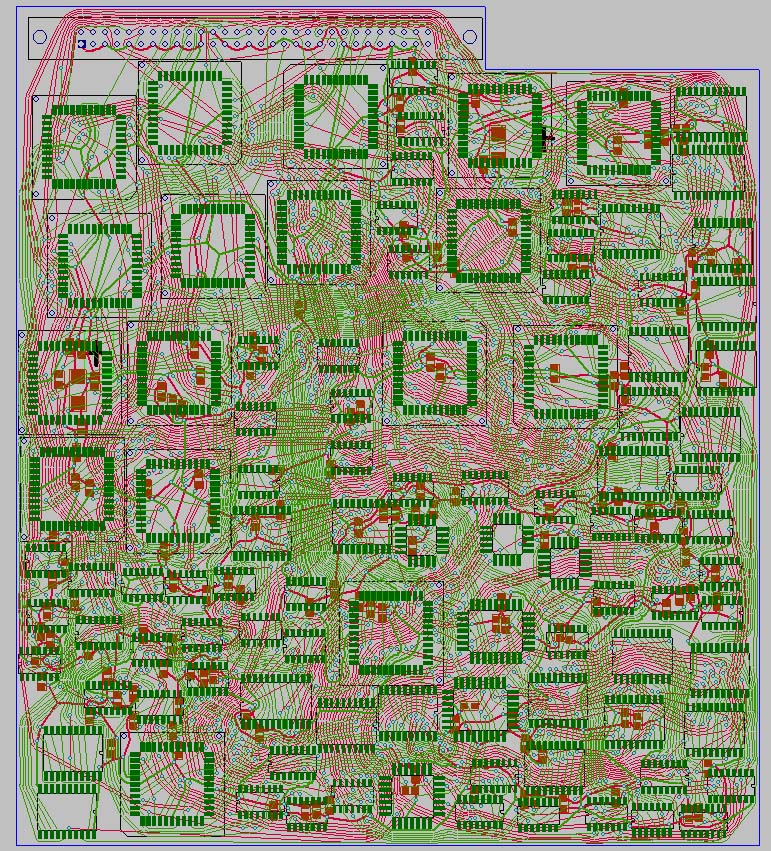
You can find below the examples of autorouting made by a popular standard autorouter and TopoR autorouter for the same board with equal technical constraints. TopoR autorouter routed the board on 2 layers instead of 8 with fewer of vias and less wires length.
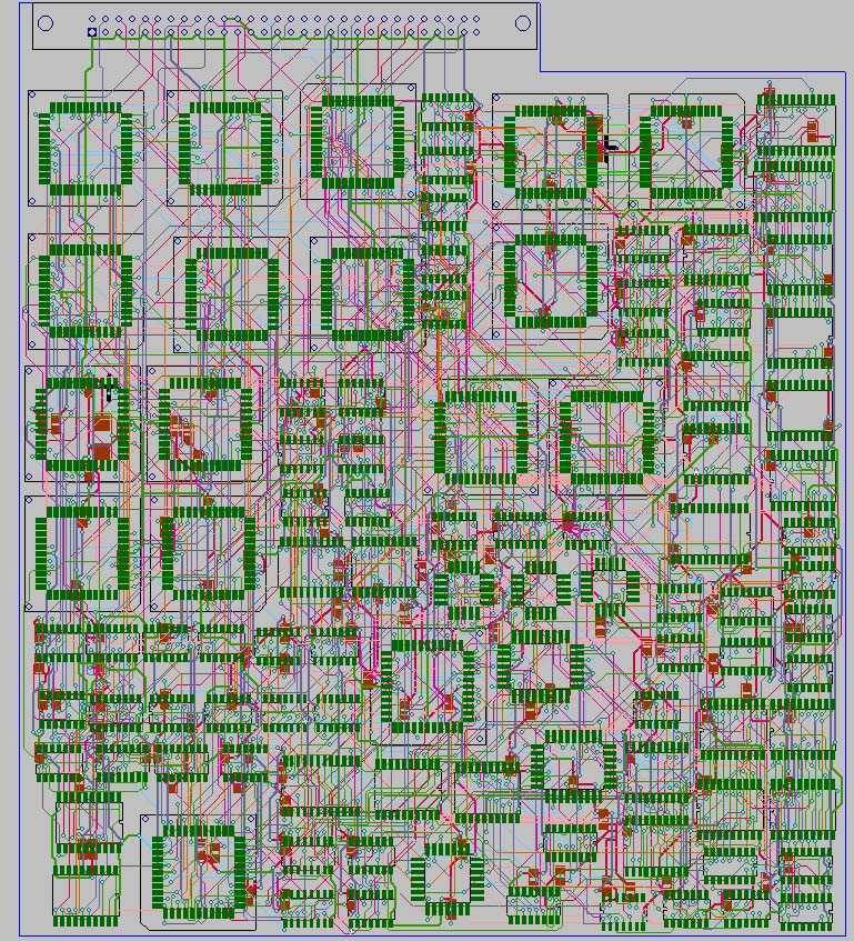 The board routed by the popular standard autorouter on 8 layers (total wire length – 48m, number of vias – 1619).
 The same board routed by TopoR autorouter on 2 layers (total wire length – 42m, number of vias – 1235.
TopoR CAD system is the leader in basic standards for complex multi-layer boards as well. The table below represents the results of comparative testing between TopoR autorouter and 3 different popular autorouters.
| TEST 1 | TEST 2 | TEST 3 | ||||
|---|---|---|---|---|---|---|
| TopoR | Popular standard router 1 | TopoR | High-class Shape-based router | TopoR | Popular standard router 2 | |
| Wires |
548 253 2588 |
1095 1131 5708 |
891 571 5050 |
|||
| Components | ||||||
| Pads | ||||||
| Vias | 1110 | 1619 | 2832 | 3932 | 1800 | 3301 |
| Layers | 2 | 8 | 4 | 4 | 4 | 4 |
| Length | 47m | 48m | 73m | 86m | 83m | 97m |
This comparative table represents the results provided by TopoR autorouter and three other popular autorouters with the same technical restraints.
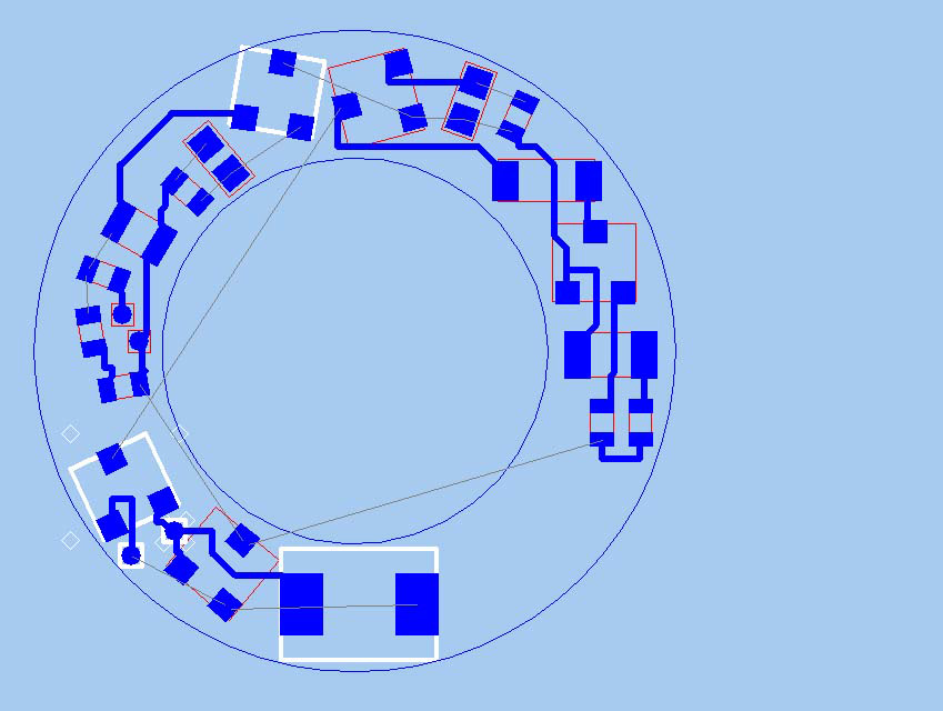
A unique quality of BGA components routing
Due to absence of preferred routing directions in layers and deep level of optimization TopoR provides quality routing of contemporary BGA components, which is traditionally a very difficult problem for other routers.
In case of using BGA components the number of layers often depends mostly on the maximum quantity of levels of such components and adopted technical design rules (minimal lead width and minimal clearance).
In a number of CAD systems BGA component internal space routing is performed according to a template, because the main purpose is to avoid blocking pads and to lead all routes to the component’s outer edges. But prescribing the mandatory routing directions results in layout deterioration and does not consider the fact that if a microchip has equipotential and non-connected pads, then in some cases the number of layers needed to provide connections can be reduced.
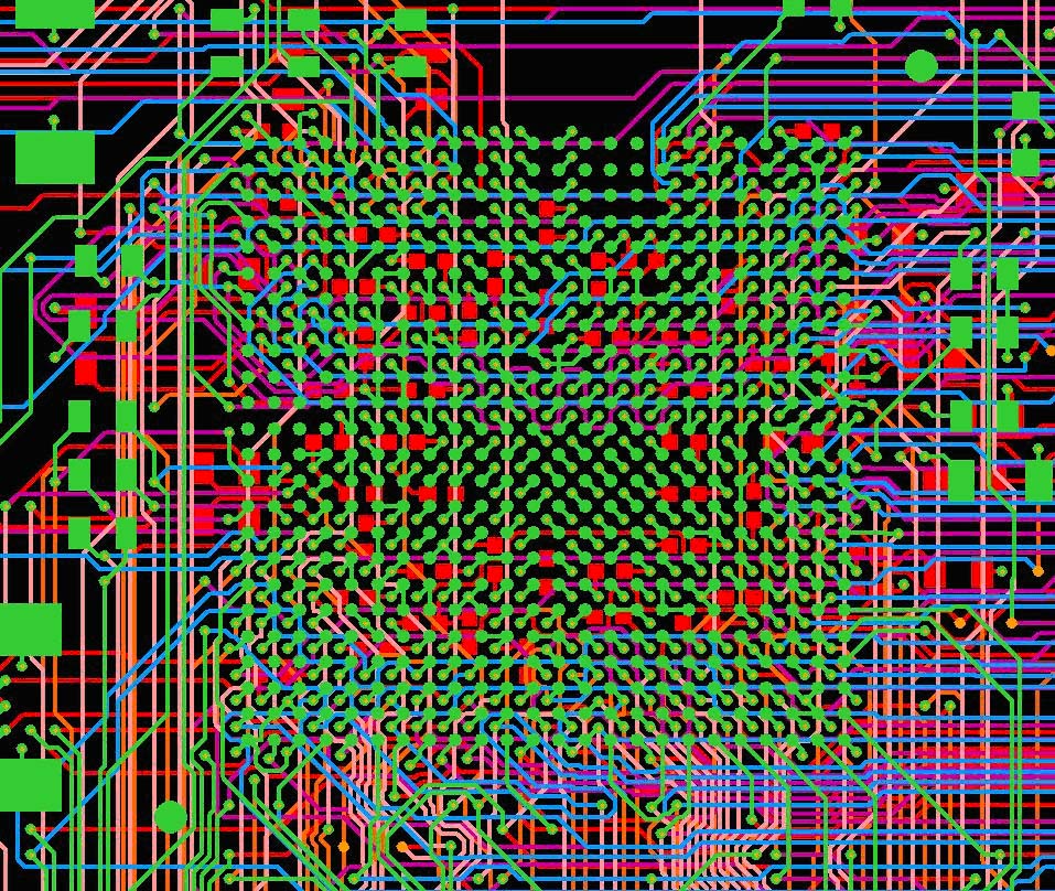
The special BGA components routing algorithms used by TopoR which consider positioning of bypass capacitors, allow to provide the best results for the most complex and saturated contemporary PCBs.
 BGA area routing performed by TopoR autorouter.
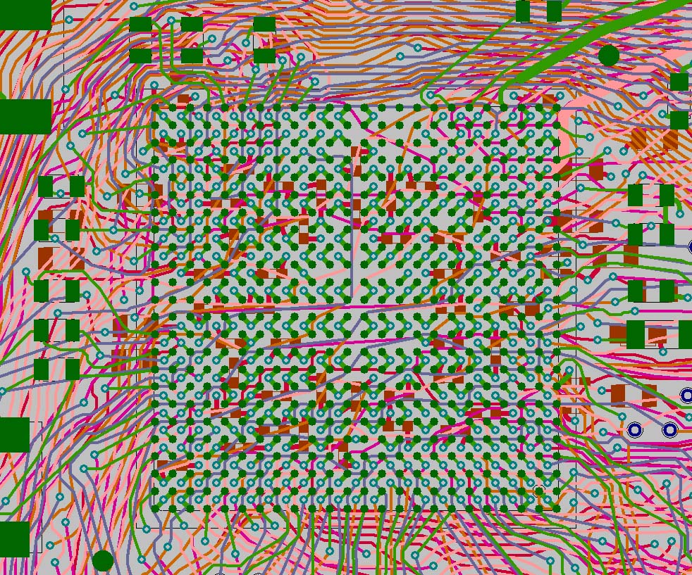
 BGA area routing performed by a high-class Shape based autorouter.
Routing quality is improved due to considering of components leads logical equivalence
One of the unique features of TopoR CAD autorouter is the ability to consider logical equivalence of components leads. The autorouter automatically moves wires from one component lead to another if this results in PCB topology optimization. All the changes are tracked in the ECO file which can then be imported to a schematic design system.
 Topology of a PCB routed without considering logical equivalence of components leads. The number of vias is 67, total wire length is 5,21 meters.
 Topology of a PCB routed with a condition of logical equivalence of all FPGA microcircuit components leads. The number of vias is 17, total wire length is 3, 79 meters.